Initial Installation
Jetson Installation
This document describes the Linux for Tegra (L4T) installation process for a custom Jetson Nano based carrier board. The packages used are derived from NVIDIA’s official releases and adapted to support board specific hardware components.
Note
The steps are written for Jetson Nano. The same procedure applies to other Jetson models; only the Ubuntu version and package names differ.
Requirements
- Jetson-210_Linux_R32.7.6_aarch64.tbz2
- Tegra_Linux_Sample-Root-Filesystem_R32.7.6_aarch64.tbz2
- Host system:
- Ubuntu 18.04
- Or Ubuntu 18.04 running inside Docker
Installation
Info
By default, the installation is performed under a workspace directory in the user’s home path. A custom directory may be used if preferred
-
Extracting the L4T Package: Create the workspace and extract the L4T package (This will create the Linux_for_Tegra directory.)
-
Installing the Root Filesystem: Extract the root filesystem into the rootfs directory:
-
Applying NVIDIA Binary Files: Run the following script to install NVIDIA-specific binaries into the root filesystem
-
Verifying the Installation: Verify that the base system was created successfully. (If the file exists, the setup is valid.)
-
Creating a Default User: To predefine the default user credentials (
-u: Username,-p: Password,-n: Hostname) -
Entering Force Recovery Mode (RCM): To flash the device, Jetson Nano must be placed into Force Recovery Mode (RCM).
- Press and hold Recovery and Reset pins together
- Wait 15–30 seconds
- Release Reset first
- Then release Recovery
- Connect the board to the host PC via USB Type-B and verify:
lsusbIf NVIDIA Corp. appears, the device is ready for flashing.
-
Flashing the Device:
FMU Firmware Installation
This section contains step-by-step instructions for flashing the bootloader and firmware onto the FMU IO (F103) and FMU MAIN (H753) chips using STM32CubeProgrammer.
Wiring — Before You Start
Before the flashing process, make sure the debug cable and the ST-Link / CubeProgrammer pins are connected correctly:
The Autopilot board must be powered (via USB or XT30) before performing these steps.
ArduPilot vs. PX4
The FMU bootloader and FMU firmware files differ depending on the autopilot software (ArduPilot or PX4). The flashing procedure remains the same — only the target files change.
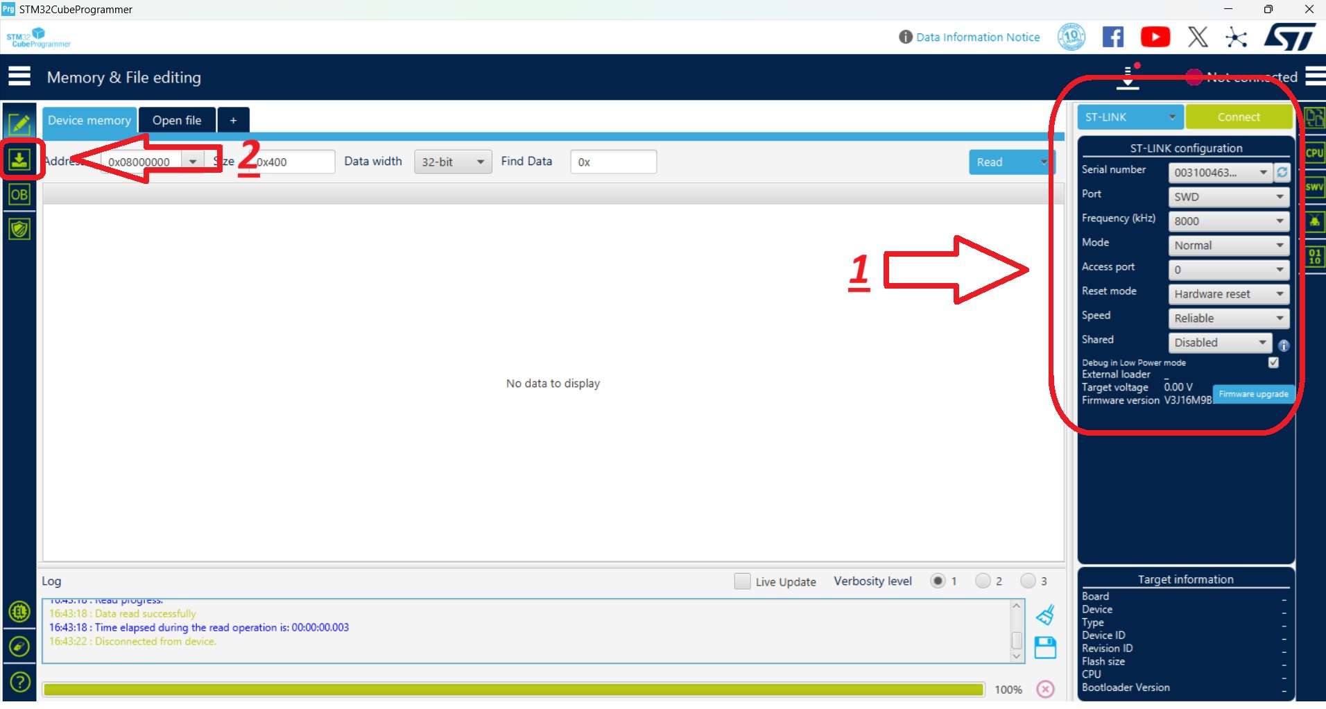
Connection Settings
Select the connection settings on the right-hand panel as shown below, then use the Connect button. After connecting, the target chip is shown in the bottom-right corner (STM32F10x for the IO chip, STM32H7 for the FMU chip).
1. IO Chip Flashing (F103)
Hardware Connections
- Connect the debug cable (10-pin GHS-10) to the IO debug port.
- Connect the ST-Link to the computer.
STM32CubeProgrammer Steps
- Launch STM32CubeProgrammer. Select the connection settings on the right panel and click Connect.
- Switch to the programming panel using the left-hand toolbar.
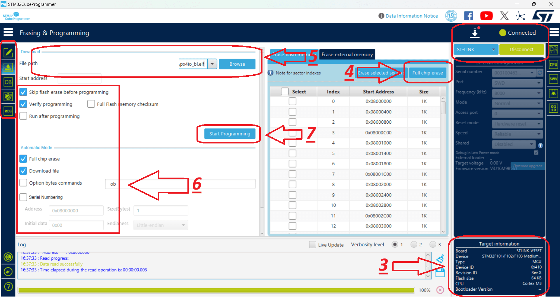
- After the ST-Link connects, verify that STM32F10x is displayed in the bottom-right corner.
- Click Full chip erase to wipe any existing code. In the confirmation pop-up ("Are you sure you want to erase full chip flash memory"), click OK.
- Select the provided IO bootloader file.
- Check the programming configuration options as indicated in the reference layout.
- Click Start Programming.
- Once complete, dismiss the "Download verified successfully" and "File download complete" alerts by clicking OK.
- The IO installation is complete.
- For safety, disconnect from the hardware by clicking Disconnect (which replaces the Connect button).
2. FMU Chip Flashing (H753)
This stage installs the Bootloader first, followed by the FMU Firmware.
Hardware Connections
- Connect the debug cable (10-pin GHS-10) to the FMU debug port.
- Connect the ST-Link to the computer.
FMU Bootloader Flashing
- Launch STM32CubeProgrammer and click Connect (top-right).
- Switch to the programming panel using the left-hand toolbar.
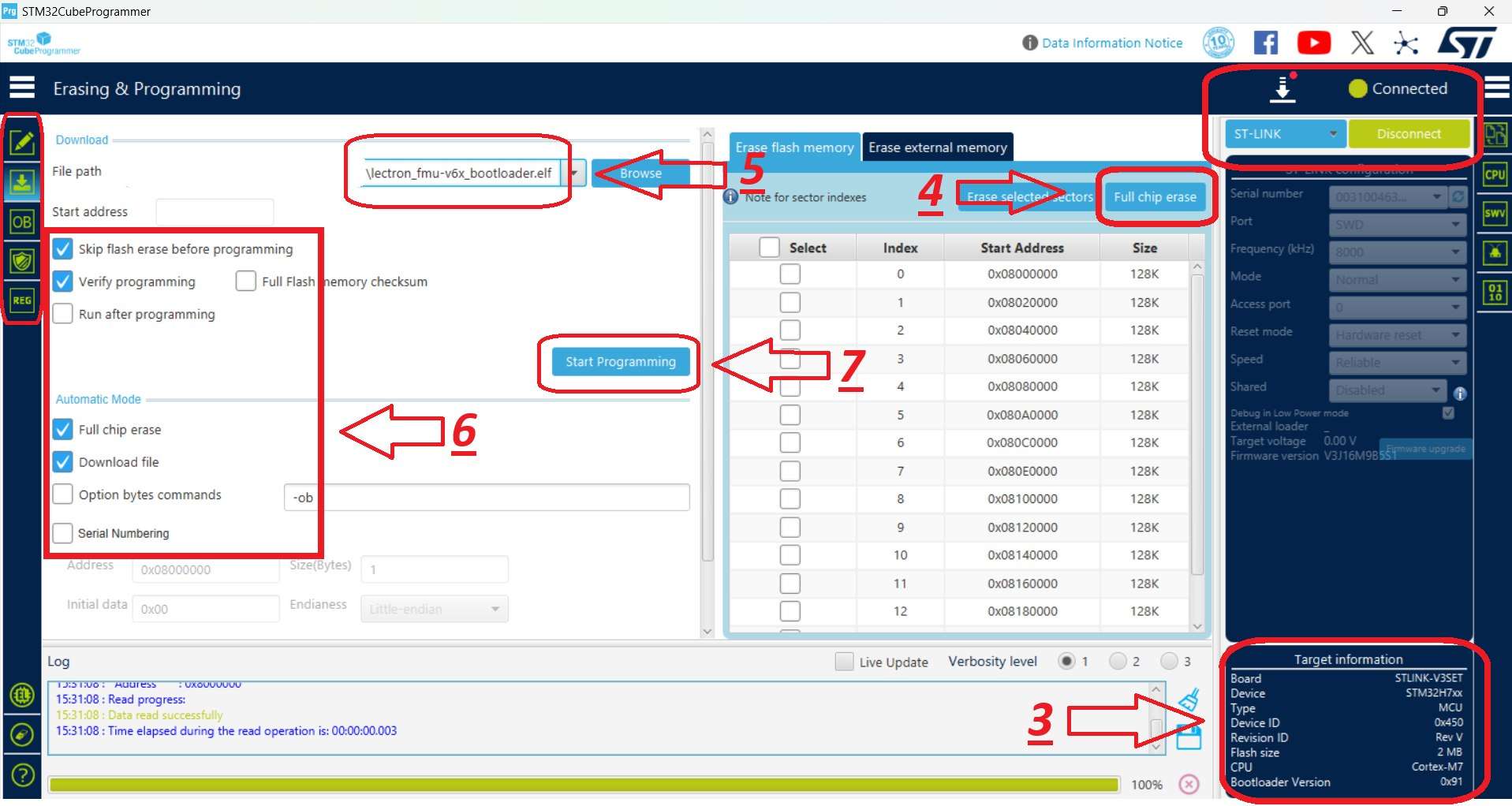
- After the ST-Link connects, verify that STM32H7 is displayed in the bottom-right corner.
- Click Full chip erase to wipe any existing code, then click OK on the confirmation pop-up.
- Select the provided FMU Bootloader file.
- Check the installation options as indicated in the reference layout.
- Click Start Programming.
- Once complete, close the "Download verified successfully" and "File download complete" prompts by clicking OK.
- The FMU Bootloader installation is complete.
- For safety, click Disconnect (top-right).
FMU Firmware Flashing
- Launch STM32CubeProgrammer and click Connect (top-right).
- Switch to the programming panel using the left-hand toolbar.
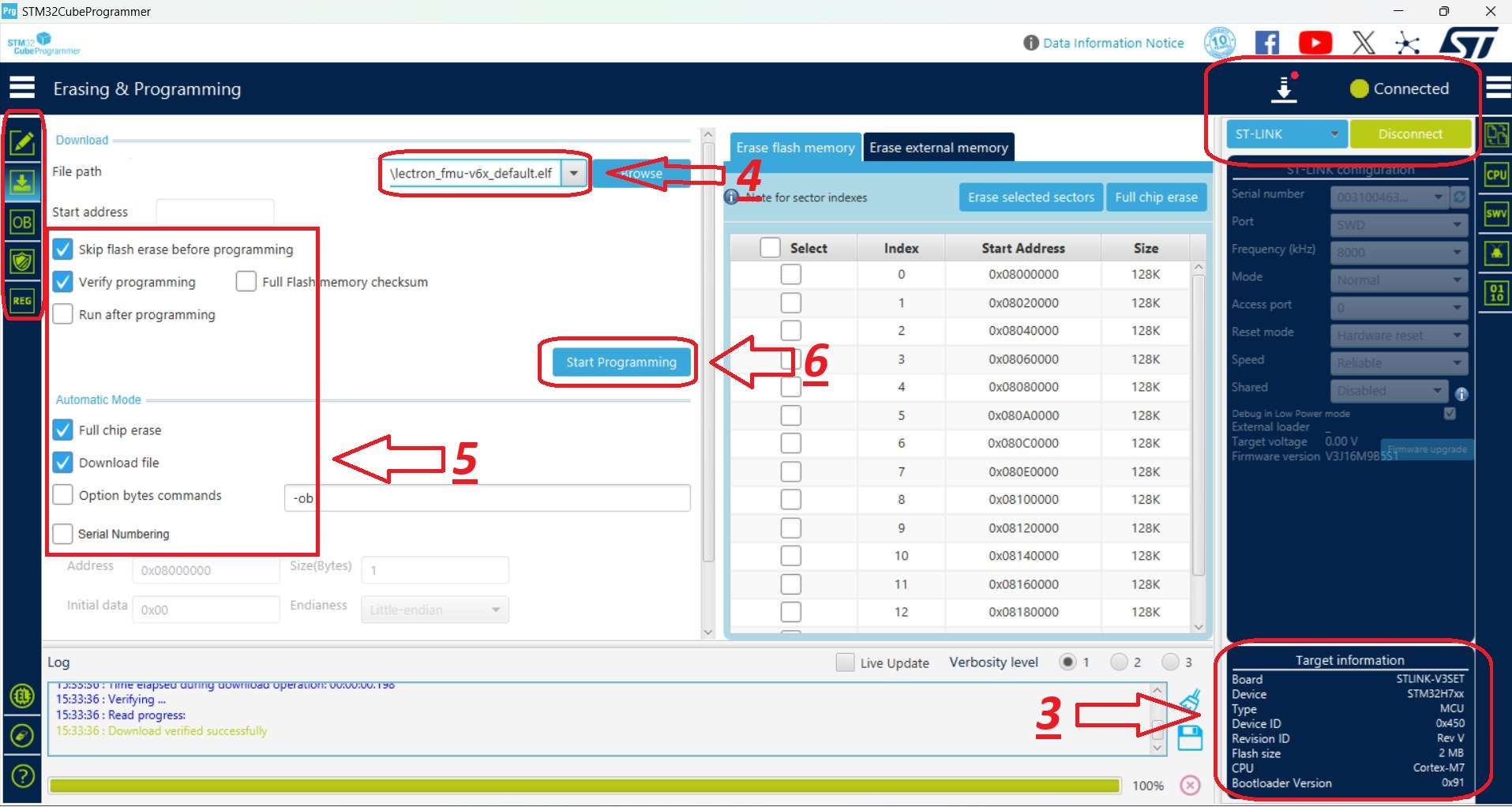
- Ensure that STM32H7 is displayed in the bottom-right corner as the target chip.
- Select the provided FMU Firmware file.
-
Check the programming options as shown in the reference image.
CRITICAL
Uncheck the Full chip erase box to prevent wiping the bootloader you just installed.
-
Click Start Programming to begin flashing the firmware.
- When the operation completes, confirm and close the "Download verified successfully" and "File download complete" alerts by clicking OK.
- The FMU Firmware installation is complete.