Assembly Guide
This guide walks through assembling the Lectron PI5 Autopilot — mounting the Raspberry Pi Compute Module 5, connecting the IMU board, and closing the enclosure.
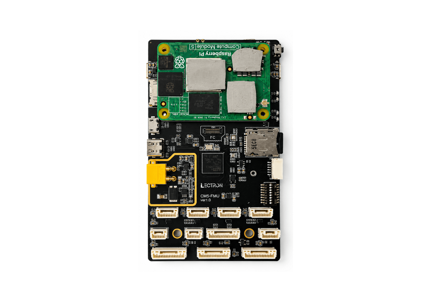
What's in the Box
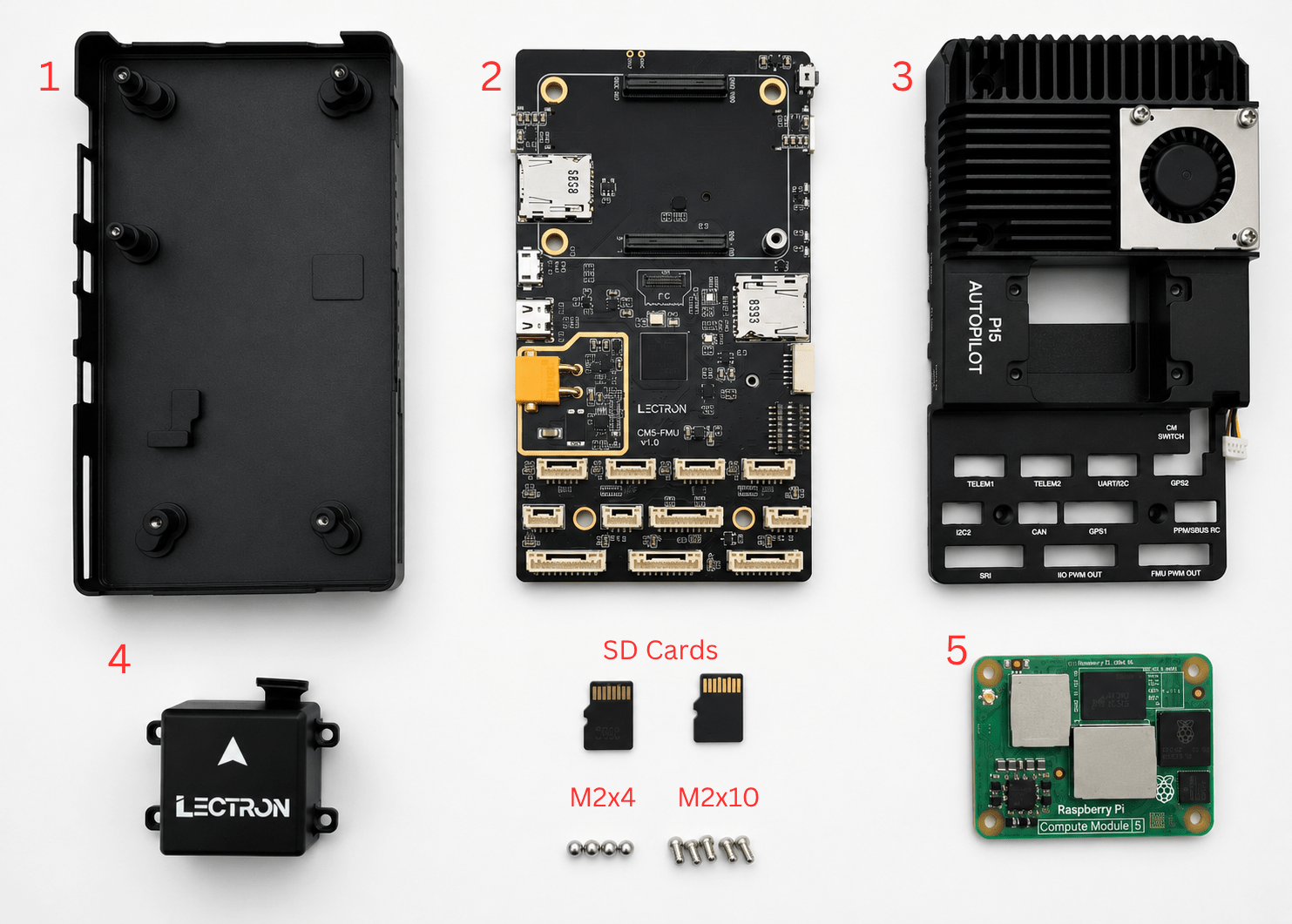
Before starting, make sure you have all of the following components:
| # | Component |
|---|---|
| 1 | Bottom case |
| 2 | CM5-FMU baseboard |
| 3 | Top case (PI5 Autopilot heatsink + fan) |
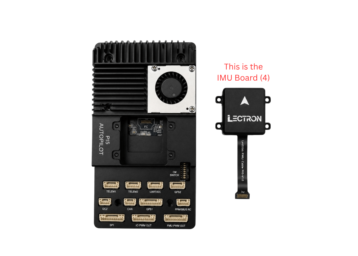
| 4 | IMU board |
| 5 | Raspberry Pi Compute Module 5 (CM5) |
| — | MicroSD card(s) |
| — | Screws: 4 pcs M2×4 mm (IMU board) and 5 pcs M2×10 mm (case) |
Step 1 — Apply the Thermal Pads
Before mounting the Compute Module 5, apply the supplied thermal pads to the CM5's chips. The pads transfer heat from the module to the top-case heatsink and are required for proper cooling.
Place a thermal pad on each of the three areas marked 1, 2, and 3 on the CM5 as shown below.
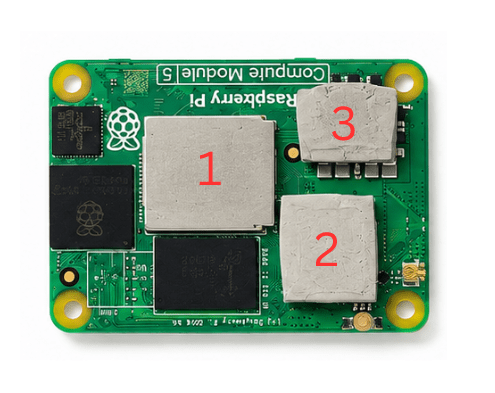
Don't Skip the Thermal Pads
Operating the CM5 without the thermal pads in place can cause the module to overheat and throttle or shut down. Make sure all three pads are fitted before mounting the module.
Step 2 — Mount the Compute Module 5
Align the CM5 with the board's connectors using the corner markings (1–4) and press it firmly onto the baseboard.
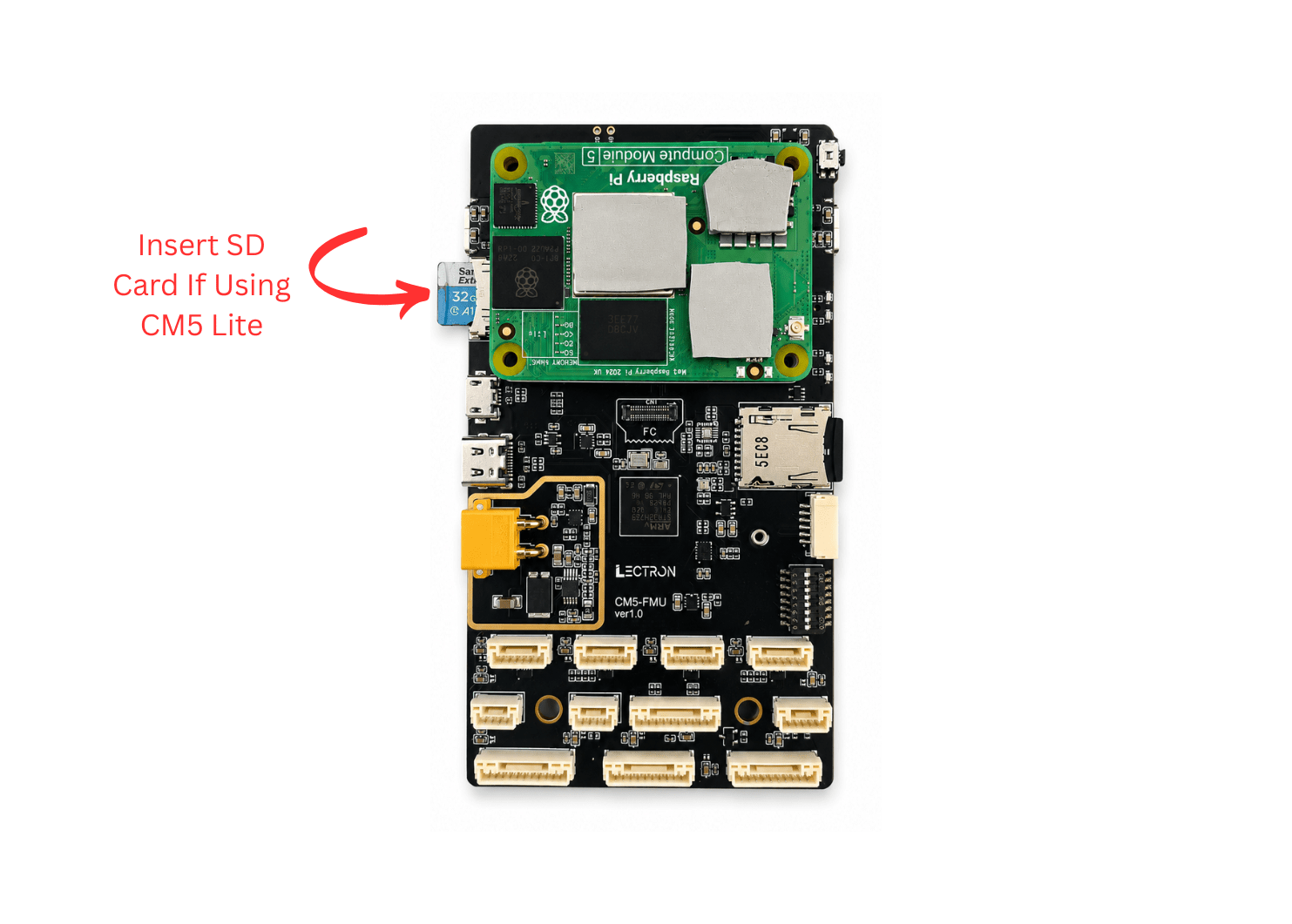
Insert an SD card into the FMU SD card slot (Insert FMU's SD Card Here).
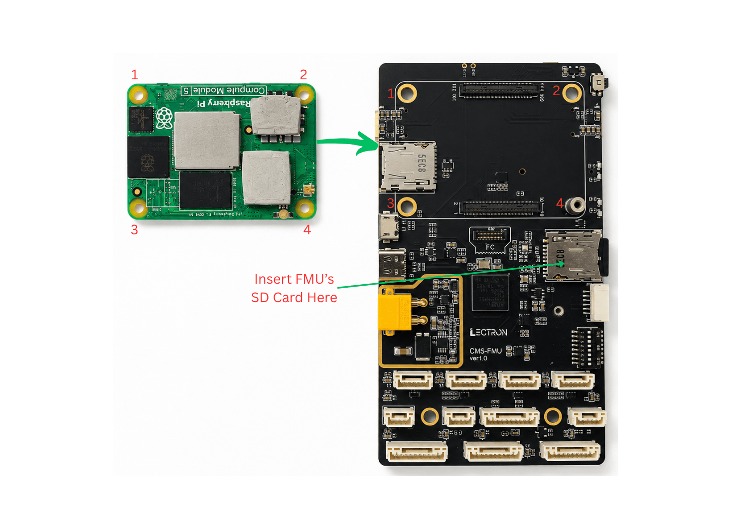
Once seated correctly, the assembly should look like this:
CM5 Lite
If you are using a CM5 Lite (no onboard eMMC), insert a microSD card into the CM5's card slot as shown below.
Install Before Closing the Bottom Case
The Hailo M.2 connector is located on the underside of the board, which becomes inaccessible once the bottom case is fitted. If you intend to use the Hailo module, install it before placing the board into the bottom case — see Hailo Integration.
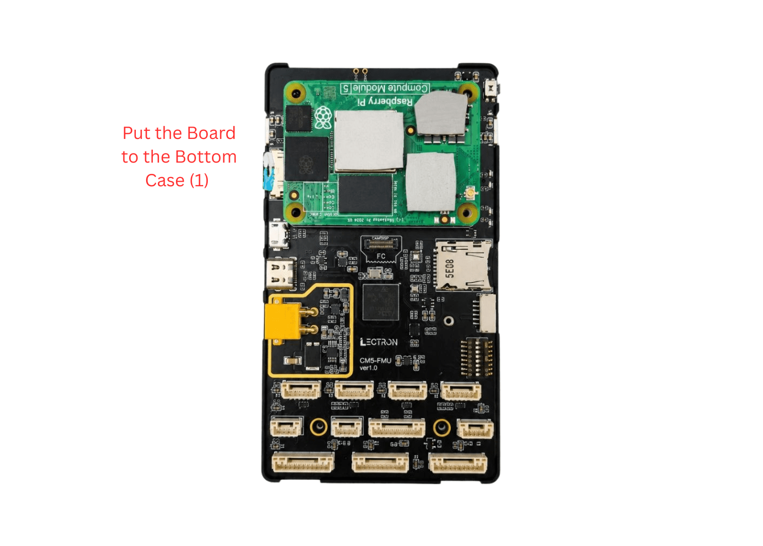
Step 3 — Place the Board in the Bottom Case
Lower the assembled baseboard into the bottom case, aligning the mounting holes.
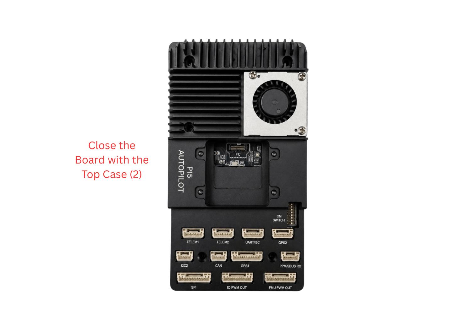
Step 4 — Close with the Top Case
Fit the top case — the P15 Autopilot heatsink and fan assembly — over the board, aligning the connector cutouts with the baseboard ports.
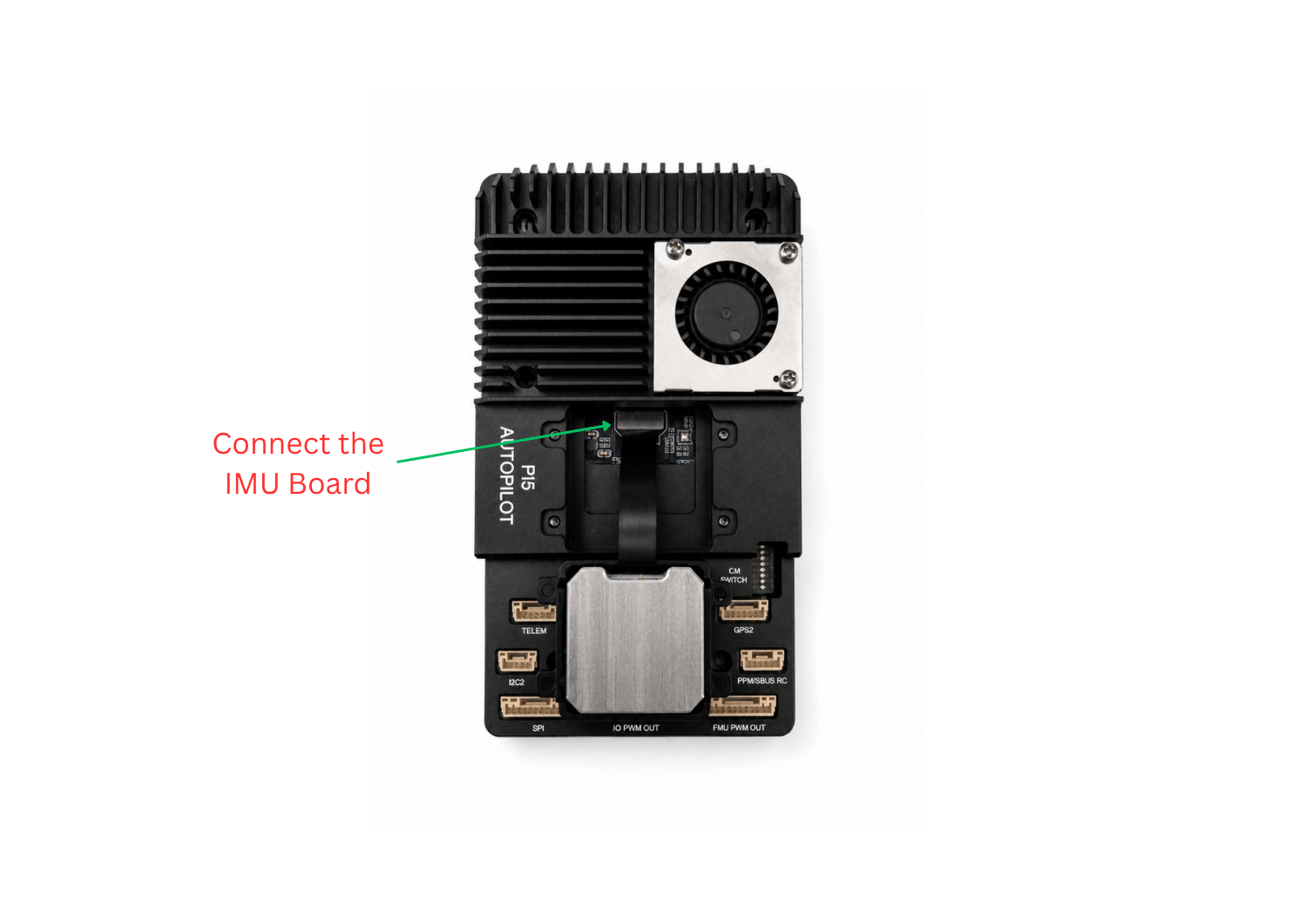
Step 5 — Connect the IMU Board
The IMU board connects to the FMU via the FPC ribbon cable.
Route the ribbon cable and connect the IMU board to the FMU connector as shown.
Handle the FPC Cable with Care
Be gentle when seating the cable into the connector — insert it straight and apply only light, even pressure. Do not bend the cable sharply, pull on it, or force it in, as this may damage the ribbon cable or the connector.
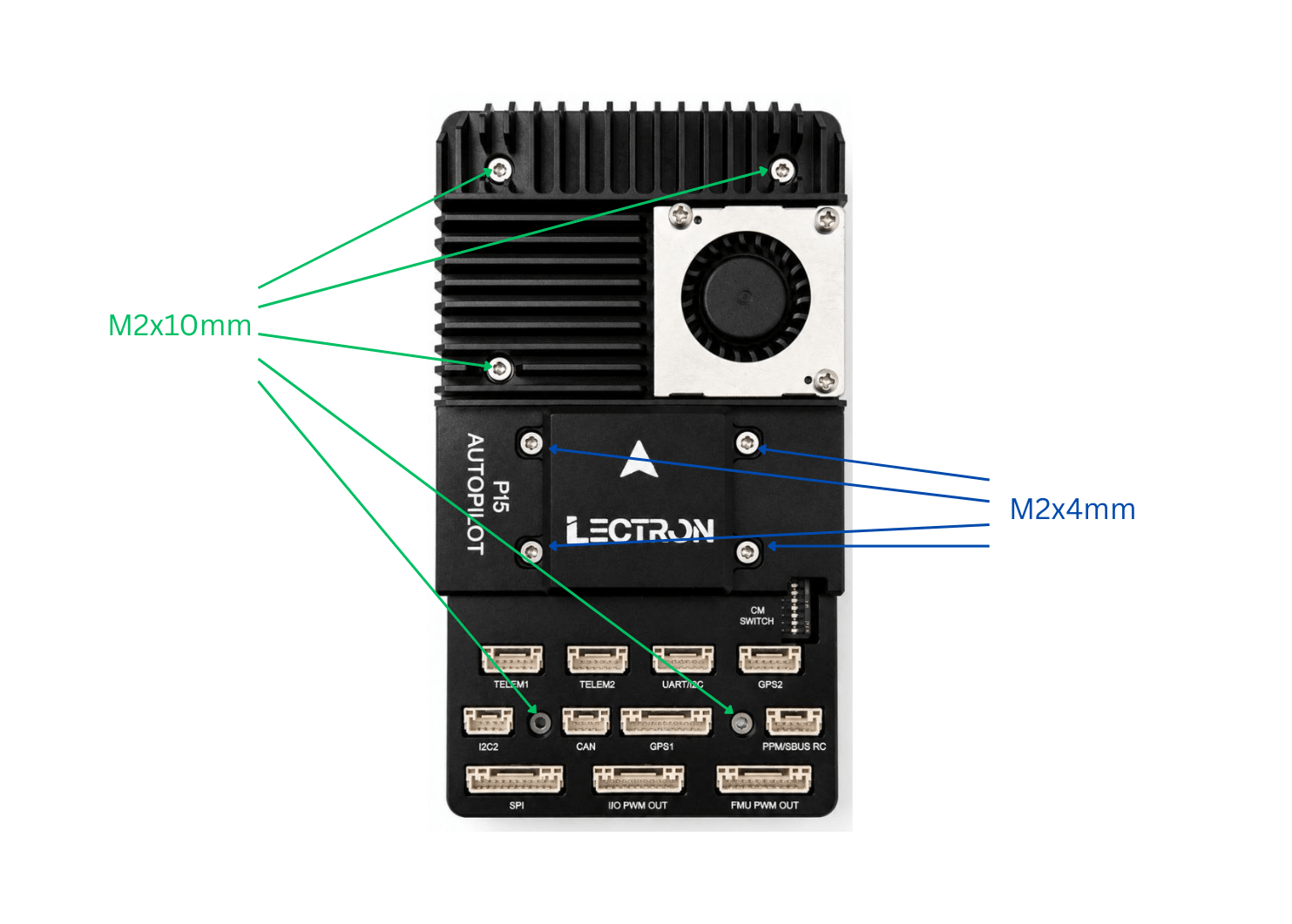
Step 6 — Fasten the Screws
Secure the assembly with the supplied screws:
- M2×10 mm — fasten the case (heatsink to baseboard / bottom case).
- M2×4 mm — secure the IMU board.
Done
The Lectron PI5 Autopilot is now assembled. Continue with the Initial Installation guide to flash the Compute Module and the FMU firmware.
Hailo Integration
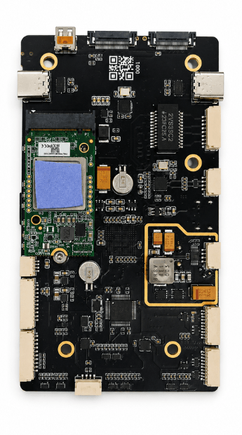
The Hailo-8 AI accelerator is installed in the M.2 M-Key slot on the CM5 carrier board.
M.2 Standoff — 2242 vs. 2230
The Lectron PI5 Autopilot ships with the M.2 M-Key standoff fitted for a 2242 module. To install a 2230 module, move this standoff from the 2242 hole to the 2230 hole. Once relocated, the board supports a 2230 build.
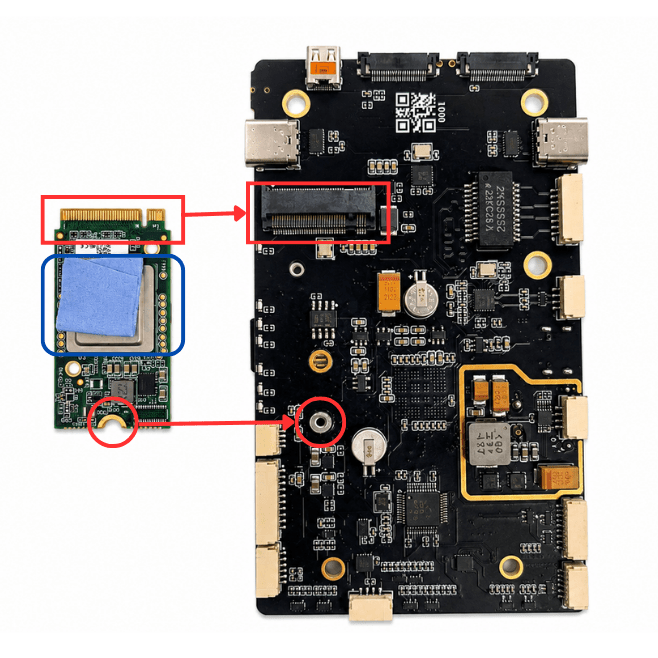
Step 1 — Locate the Connector, Screw and Thermal Pad
The image below shows the Hailo module and the CM5 carrier board. The red rectangles mark the M.2 connector, the red circles mark the standoff/screw locations, and the blue rectangle marks where the thermal pad must be applied on the Hailo module.
Apply the Thermal Pad
Before installing the Hailo module, apply a thermal pad to the area marked by the blue rectangle on the module. The pad is required for proper heat dissipation — operating the Hailo-8 without it can cause overheating and thermal throttling.
Step 2 — Insert the Module
Hold the Hailo module at a slight incline, align its M.2 edge connector with the slot, and push it firmly into the connector.
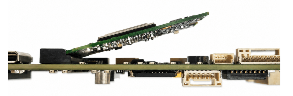
Insert Carefully
Be careful and gentle while pushing the module into the connector.
Step 3 — Fasten the Screw
Press the module down until it lies flat against the standoff, then fasten the screw at the location marked by the red circle in Step 1. The fully installed module is shown below.